At the core of the instrument is a central optical breadboard that carries the laser emitter, receiver module, scanner and the three lens telescopes. This breadboard provides a rigid common reference so that external mechanical loads on the housing do not disturb internal alignment.
The breadboard is mounted in a 3D‑printed frame made from graded thermoplastics (standard, engineering and high‑performance plastics) chosen for stiffness, low weight and low outgassing. Power electronics, the chiller interface and control hardware are arranged in the lower compartment; the optical section sits above.
The housing is heavily insulated on all sides. A guided internal airflow, driven by the chiller, keeps the optical section within ±1 °C even when the external temperature ranges from 0 to 35 °C and local surfaces reach up to 50 °C in direct sun. Field tests showed that painting the 3D‑printed exterior reduces surface temperatures from >80 °C to ~40 °C.
A sliding top cover protects the telescopes against rain and snow. In both open and closed positions it does not extend beyond the instrument’s footprint, which minimizes wind shear loads. The platform is mounted on an elevated metal structure (~1 m above ground) to avoid near‑ground turbulence and snow accumulation; this structure has already withstood storms with gusts >180 km/h while the lidar operated safely up to ~130 km/h before automatic shutdown.
All structural parts have been 3D‑printed and assembled, and one complete platform has been operated outdoors for several months, demonstrating thermal stability, weather tightness and mechanical robustness.
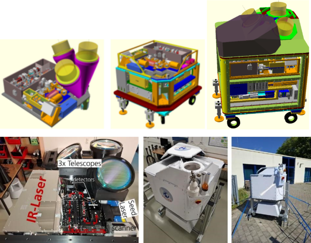
above: CAD of: central breadboard with all subsystems attached, breadboard integrated into lidar platform without structural parts, full lidar platform with top cover
below: Photos of: platform with subsystems, fully assembled lidar, lidar during atmospheric tests